
Brookline Industries • 1624 South Clinton Street • Chicago, Illinois USA 60616
Single and Double Magnetic Door Locks
1 - Description
The Electromagnetic Lock (Maglock) series is a surface mounted magnetic lock assembly. Available in single and dual lock varieties and various sizes (force) designed for standard installation on most types of doors.
 |
 |
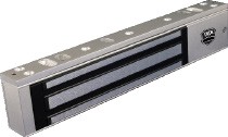
| SINGLE 10MAGLOCK1UL |
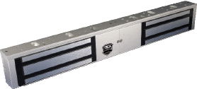
DOUBLE 10MAGLOCK5UL |
2 - Specifications
| DESCRIPTION | 10MAGLOCK1UL | 10MAGLOCK5UL |
| Lock | Single | Double |
| Input Voltage (VDC) | 12 or 24 | 12 or 24 |
| Relay Rating @ 24 VDC: (amps) | 1.0 | 1.0 |
| Dimensions: Inches and (mm) | 10.47 x 2.87 x 1.58 (266 x 73 x 1.58) |
21.28 x 2.87 x 1.58 (532 x 73 x 40) |
ATTENTION: This product must be powered from a UL listed power supply!
3 - Precautions
- Shut off all power before attempting any wiring procedures.
- Maintain a clean & safe environment when working in public areas.
- Constantly be aware of pedestrian traffic around the door area.
- Always stop pedestrian traffic through the doorway when performing tests that may result in unexpected reactions by the door.
- Always check placement of all wiring before powering up to insure moving door parts will not catch any wires and cause damage to equipment.
- Ensure compliance with all applicable safety standards and building codes upon completion of installation.

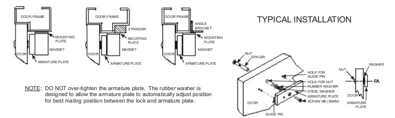
4 - Installation - Mechanical
- Handle the equipment with care. Damaging the mating surfaces of the magnet and armature plate may reduce locking efficiency.
- The maglock mounts rigidly to the door frame. The armature plate mount to the door with the hardware provided. This allows the armature plate to pivot about its center to compensate for door wear and misalignment.
- Template usage must take place with the door in its normally closed position.
- Add threadlocker to all screws before installing.
- Firmly tighten screws.
5 - Installation - Electrical
NOTE: The product should only be powered by a UL listed power supply.
NOTE: If power switch is not wired between DC source voltage and magnet, it will take a longer time to de-energize the magnet simulating residual magnetism.
CAUTION: Observe proper circuit board orientation.

- 12 VDC Input
- Required power 0.5A (Max).
- Connect ground (-) lead from a 12 VDC power source to Terminal 2.
- Connect positive (+) lead from a 12 VDC power source to terminal 1.
- Check Jumper for 12 VDC operation.
- 24 VDC Input
- Required power 0.25A (Max).
- Connect ground (-) lead from a 24 VDC power source to Terminal 2.
- Connect positive (+) lead from a 24 VDC power source to Terminal 1.
- Check Jumper for 24 VDC operation.
- Contacts
- Relay dry contacts are rated 1A at 24 VDC for safe operation, DO NOT exceed this rating.
- If a NO switch is required, connect the wires from the system to Terminal 4 amp; Terminal 3.
- If a NC switch is required, connect the wires from the system to Terminal 4 amp; Terminal 5.